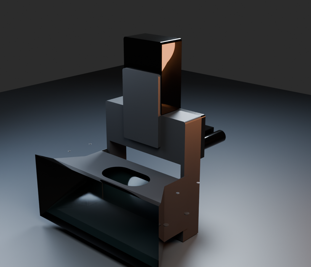
Precision mechanics
The five-axis rig
A compact beam-splitter architecture designed around controlled movement and repeatable optical alignment.
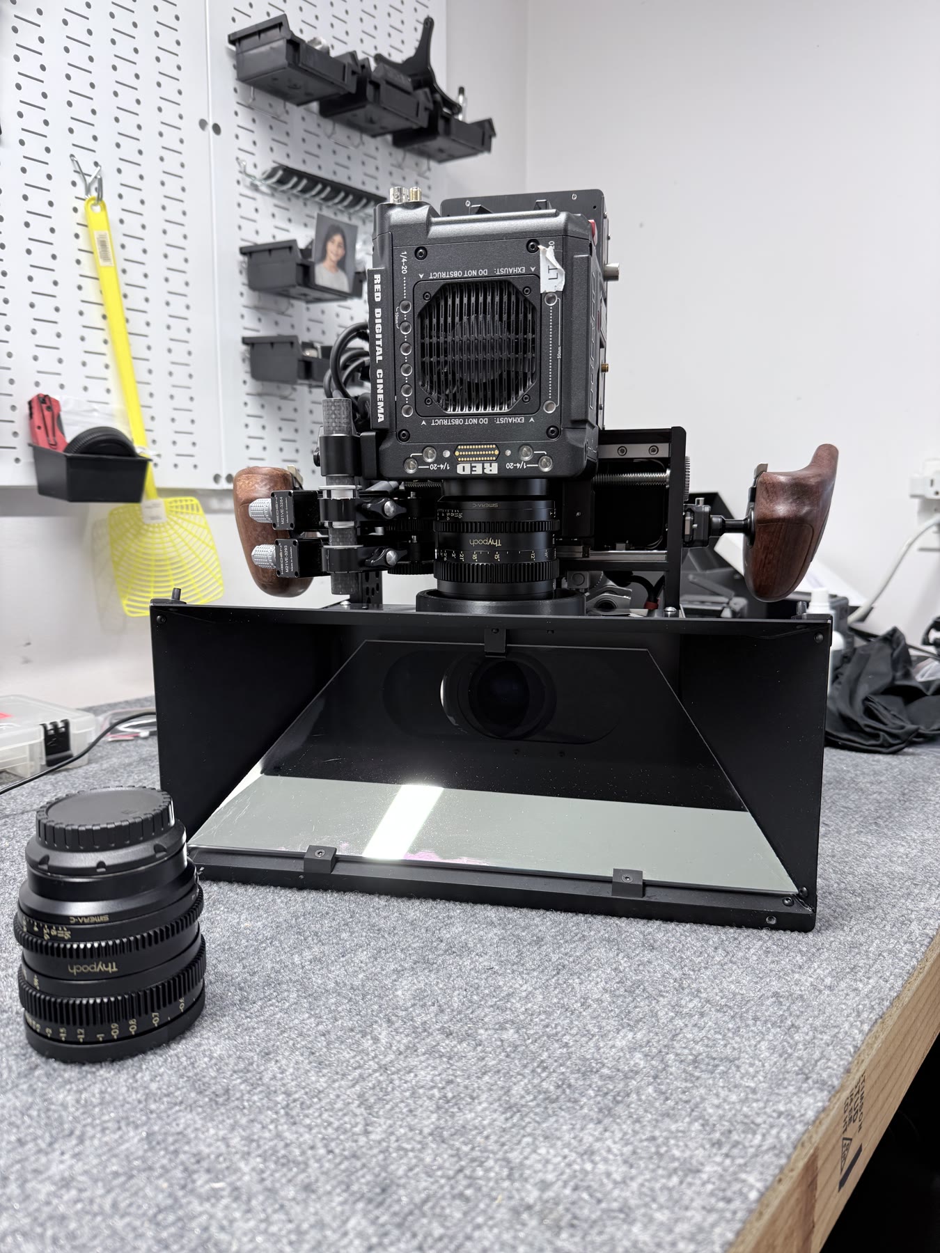
Five-axis stereoscopic camera platform
Project Atlas brings rig movement, optics, camera control, timecode, and positional metadata into one coordinated production system—built to make sophisticated stereo work practical on set.
01 / Front optical path
The rig is not a collection of isolated mechanisms. Tilt, height, roll, interaxial, and convergence work as one system around the optical path.
Designed to turn complex stereoscopic alignment into a repeatable production workflow.
A compact beam-splitter architecture designed around controlled movement and repeatable optical alignment.
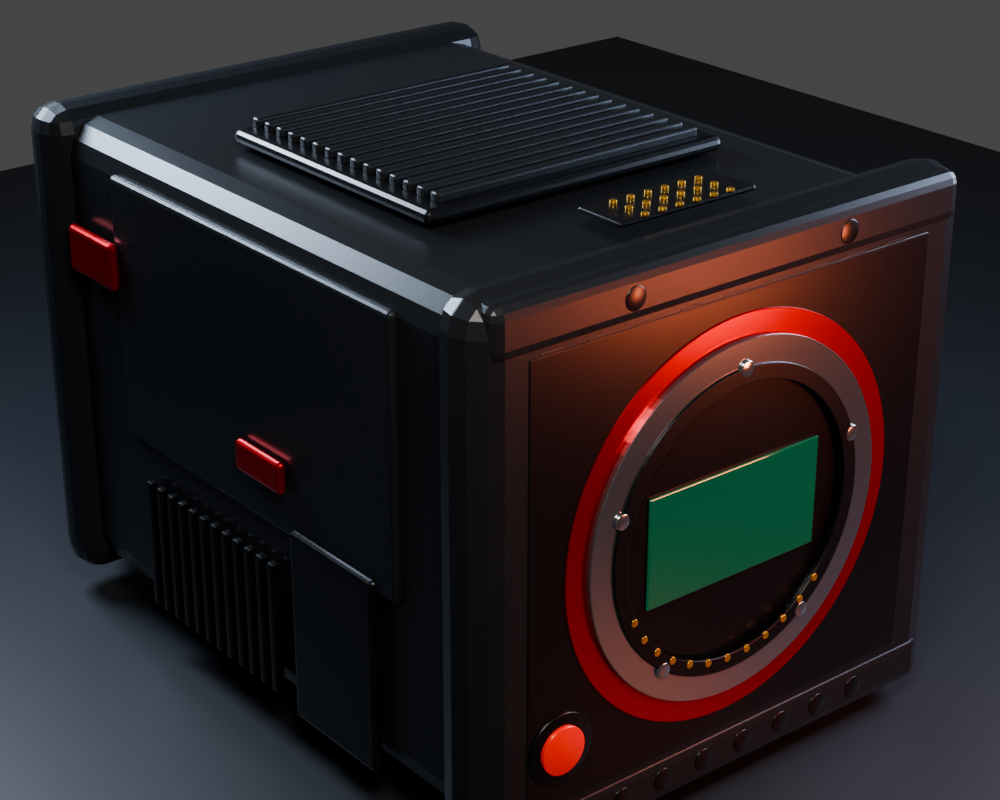
True-scale camera bodies and mounts make the digital system useful for real configuration work.
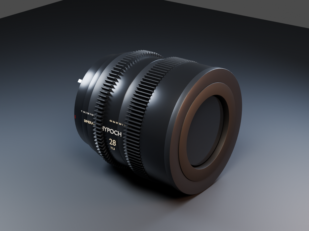
Optical components share a common origin and scale so clearances can be understood before the physical build.
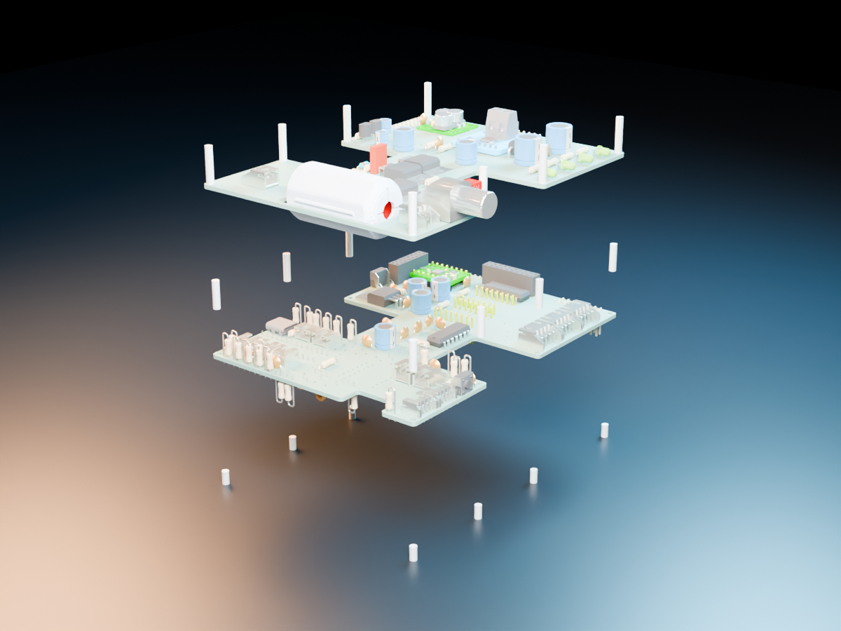
Controller, driver, and power boards form a serviceable stack built to coordinate the moving system.
Rotate and inspect the supplied Eclipse CAD model with reference-matched PBR finishes for anodized aluminum, powder-coated panels, carbon fiber, stainless hardware, and optical glass.
The detailed FBX contains three real assemblies—the controller, driver, and power boards—plus their modeled components, spacers, and fasteners. Use the controls to inspect the assembled stack or move through the exploded sequence.
Mechanics, optics, electronics, software control, timecode, and motor-position metadata are being developed as one stereo-production platform—not separate accessories.
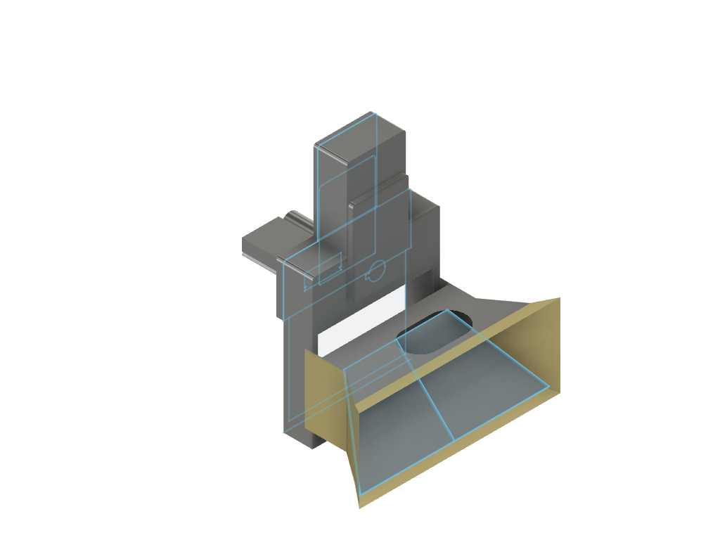
Optical reference
The next model passes can add named components, axis movement, and separate exploded mechanical and electronics views.
Physical rig control remains private and authenticated.